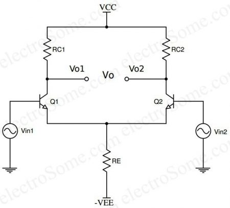
Vi1 and Vi2 are input terminals and Vo1 and Vo2 are output terminals with respect to ground. We can feed two input signals at the same time or one at a time. In the former case it is called dual input otherwise it is single input. Similarly there are two ways to take output also. If the output is taken from one terminal with respect to ground, it is unbalanced output or if the output is taken between two output terminals, it is balanced output.
Differential Amplifier using BJT
The simplest form of differential amplifier can be constructed using Bipolar Junction Transistors as shown in the below circuit diagram. It is constructed using two matching transistors in common emitter configuration whose emitters are tied together.
Configurations
Based on the methods of providing input and taking output, differential amplifiers can have four different configurations as below.
Single Input Unbalanced Output
Single Input Balanced Output
Dual Input Unbalanced Output
Dual Input Balanced Output
Single Input Unbalanced Output
In this case, only one input signal is given and the output is taken from only one of the two collectors with respect to ground as shown below.
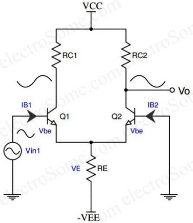
When input signal Vin1 is applied to the transistor Q1, it’s amplified and inverted voltage gets generated at the collector of the transistor Q1. At the same time it’s amplified and non-inverted voltage gets generated at the collector of the transistor Q2 as shown in the above diagram. Unbalanced output will contain unnecessary dc content as it is a dc coupled amplifier therefore this configuration should follow by a level translator circuit.
How the transistor Q2 also producing output voltage even though the input is provided only to transistor Q1 ?
The effect of input voltage Vin1 is coupled to the transistor Q2 via the common emitter resistor RE.